We have seen how standard L3 MPLS works in the previous post http://ciskonetwork.blogspot.co.uk/2015/03/layer-3-mpls-vpn.html.
In normal implementation, customer sites are served by a single service provider. The PE routers maintain an IBGP session and the routing information gets exchanged through VPNv4 neighbourship.
What if two customer sites are connected through different service providers? The PE routers of each service provider will not be able to establish IBGP neighbourship with each other hence won't be able to exchange VPNv4 routes.
There are mainly three ways to handle this type of a situation. One of three methods is called "Option A - Back to Back VRF".

As depicted in the diagram, we have two service providers SP1 and SP2 with BGP AS number 100 and 200 respectively.
CE1 is connected to SP1 PE device and CE2 is connected to SP2 PE device. The SP1-P and SP2-P are normal P routers in the core.
SP1 is running OSPF as IGP and SP2 is using ISIS.
SP1 and SP2 peer with each other through a boundary router shown as SP1-ASBR and SP2-ASBR.
Let's first check the config of CE1 and CE2.


CE1 and CE2 has standard EBGP neighbourship with corresponding PE routers. There is a loopback on each CE which is advertised through the BGP process. Our aim is to establish reachability between loopback IPs.
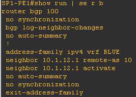
On the SP1-PE1, we have configured a VRF named "BLUE". The interface connecting to CE1 is part of this VRF and we have configured BGP neighbourship with CE1.


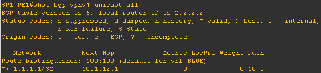
We can also see that SP1-PE1 receives the loopback prefix 1.1.1.1/32 from CE1.
Similarly on SP2-PE1, we have configured a VRF named "RED" and established BGP neighbourship with CE2. PE router is learning the loopback 8.8.8.8/32 from CE2.


In normal MPLS L3 VPN, we would have to configure VPNv4 neighbourship between both the PEs and advertise the routes. However in this case, the PEs are in different Autonomous system so that's not possible.
As shown in the diagram, SP1-ASBR and SP2-ASBR are on the edge of service provider network so we have to consider them as the PE devices where the end customer connects.
Let's establish VPNv4 neighbourship between SP1-PE and SP1-ASBR.
We need to configure loopback on SP1-PE1 and SP1-ASBR and advertise into OSPF as well.


We also have to configure VRF "Blue" with appropriate RT values on SP1-ASBR.

Now we will configure VPNv4 neighbourship and advertise the customer routes.


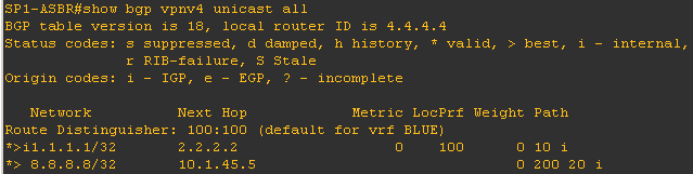
SP1-ASBR has now started learning the customer prefix 1.1.1.1/32.

Similarly we need to configured devices in SP2 network.
Let's create VRF "RED" on SP2-PE1, assign the interface facing CE2 in the VRF, establish BGP neighbourship and make sure the prefix 8.8.8.8/32 is learned via BGP.


We need to establish the VPNv4 neighbourship between SP2-PE1 and ASBR-P2 as we did for SP1.
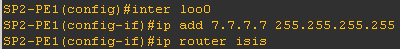
First create the loopback on both the routers and enable ISIS.

Now configure VRF "RED" on SP2-ASBR.

Next step is to configure VPNv4 neighbourship.


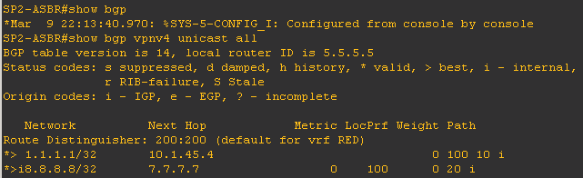
SP2-ASBR has started learning the customer prefix 8.8.8.8/32.

In "Option A", the ASBR router treats the connected service provider router as customer device so from SP1 prospective SP1-ASBR will act as the PE and SP2-ASBR will act as the CE and vice versa.
If there are multiple customers (multiple VRFs), we can configure subinterfaces to exchange the routing information for each customer.
In this scenario, let's use VLAN 100. We will configure sub interface on both the ASBR routers and put them under the appropriate VRF.


Just like any PE-CE routing, we can now run any IGP or BGP to exchange the routing information.
Let's use standard BGP here.


ASBRs have started exchanging routing information.
These routing updated should have been passed onto the CE1 and CE2.

We can now verify the connectivity end to end.
"Back to back VRF" is the most simplest method to implement hence it's widely used in real world.
The drawback of this method is that there will be no end-to-end LSP as the ASBRs have standard IP connectivity i.e. MPLS is not enabled on the link between ASBRs.
Also for each and every customer, service provider will have to maintain a separate subinterface and the full routing table on the ASBR so scalability can be an issue.
In normal implementation, customer sites are served by a single service provider. The PE routers maintain an IBGP session and the routing information gets exchanged through VPNv4 neighbourship.
What if two customer sites are connected through different service providers? The PE routers of each service provider will not be able to establish IBGP neighbourship with each other hence won't be able to exchange VPNv4 routes.
There are mainly three ways to handle this type of a situation. One of three methods is called "Option A - Back to Back VRF".

As depicted in the diagram, we have two service providers SP1 and SP2 with BGP AS number 100 and 200 respectively.
CE1 is connected to SP1 PE device and CE2 is connected to SP2 PE device. The SP1-P and SP2-P are normal P routers in the core.
SP1 is running OSPF as IGP and SP2 is using ISIS.
SP1 and SP2 peer with each other through a boundary router shown as SP1-ASBR and SP2-ASBR.
Let's first check the config of CE1 and CE2.
CE1 and CE2 has standard EBGP neighbourship with corresponding PE routers. There is a loopback on each CE which is advertised through the BGP process. Our aim is to establish reachability between loopback IPs.
On the SP1-PE1, we have configured a VRF named "BLUE". The interface connecting to CE1 is part of this VRF and we have configured BGP neighbourship with CE1.
We can also see that SP1-PE1 receives the loopback prefix 1.1.1.1/32 from CE1.
Similarly on SP2-PE1, we have configured a VRF named "RED" and established BGP neighbourship with CE2. PE router is learning the loopback 8.8.8.8/32 from CE2.
In normal MPLS L3 VPN, we would have to configure VPNv4 neighbourship between both the PEs and advertise the routes. However in this case, the PEs are in different Autonomous system so that's not possible.
As shown in the diagram, SP1-ASBR and SP2-ASBR are on the edge of service provider network so we have to consider them as the PE devices where the end customer connects.
Let's establish VPNv4 neighbourship between SP1-PE and SP1-ASBR.
We need to configure loopback on SP1-PE1 and SP1-ASBR and advertise into OSPF as well.
We also have to configure VRF "Blue" with appropriate RT values on SP1-ASBR.
Now we will configure VPNv4 neighbourship and advertise the customer routes.
SP1-ASBR has now started learning the customer prefix 1.1.1.1/32.
Similarly we need to configured devices in SP2 network.
Let's create VRF "RED" on SP2-PE1, assign the interface facing CE2 in the VRF, establish BGP neighbourship and make sure the prefix 8.8.8.8/32 is learned via BGP.
First create the loopback on both the routers and enable ISIS.
Now configure VRF "RED" on SP2-ASBR.
Next step is to configure VPNv4 neighbourship.
SP2-ASBR has started learning the customer prefix 8.8.8.8/32.
In "Option A", the ASBR router treats the connected service provider router as customer device so from SP1 prospective SP1-ASBR will act as the PE and SP2-ASBR will act as the CE and vice versa.
If there are multiple customers (multiple VRFs), we can configure subinterfaces to exchange the routing information for each customer.
In this scenario, let's use VLAN 100. We will configure sub interface on both the ASBR routers and put them under the appropriate VRF.
Just like any PE-CE routing, we can now run any IGP or BGP to exchange the routing information.
Let's use standard BGP here.
ASBRs have started exchanging routing information.
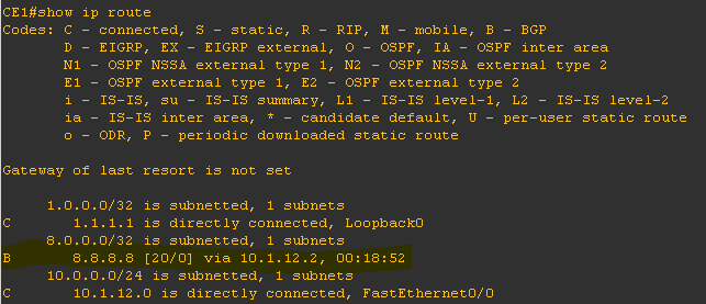
These routing updated should have been passed onto the CE1 and CE2.
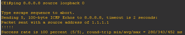
We can now verify the connectivity end to end.
"Back to back VRF" is the most simplest method to implement hence it's widely used in real world.
The drawback of this method is that there will be no end-to-end LSP as the ASBRs have standard IP connectivity i.e. MPLS is not enabled on the link between ASBRs.
Also for each and every customer, service provider will have to maintain a separate subinterface and the full routing table on the ASBR so scalability can be an issue.
Hey you ommit a lot of configuration, if you try to reply your lap using only the things that you are showing is not enough, you are skipping important steps and configs, it's a good explanation but there is still missing some important things
ReplyDelete