6VPE (IPv6 VPN Provider Edge Router) is a feature which connects the customer sites configured with IPv6 addressing over the existing IPv4 MPLS backbone.
In our last post, we have seen how we can configure standard Layer 3 MPLS connection on Cisco routers and advertise customer's IPv4 prefixes over that.
We will use the same topology for 6VPE however we will configure IPv6 addresses between PE to CE (R1-R2 and R5-R6) and on the Loopbacks of the CEs (R1 and R6).
This is how our topology looks like
We have used IPv6 ranges 2001:AA12::/64 between R1-R2 and 2001:BB56::/64 between R5-R6.
The loopbacks have been configured with 2001:1111::1/64 and 2001:6666::6/64 on R1 and R6 respectively.
Our aim to establish connectivity between these loopbacks over the backbone which is configured with IPv4 and runs OSPF+MPLS.
Ok so let's start the configuration
1. First, we will enable the IPv6 routing on CEs and configure the required interfaces with IPv6 addresses.
2. Now we will enable IPv6 on PEs and configured address-family IPv6 for VRF CUST1.
To support IPv6 VRF, we will remove the existing "ip vrf CUST1" configuration and reconfigure VRF with "VRF definition" command.
We have used RD as 100:1 and RT value for both import and export as 100:100. If we need to configure the IPv4 parameters for VRF CUST1, it can be done under "address-family ipv4".
Let's apply the similar config on R5.
Now we will configure the CPE facing interfaces with IPv6 addresses and make sure the basic reachability is there.
3. The next step is to establish BGP neighbourship between PE and CE and advertise loopback IP from the CEs.
On the CEs
On the PEs
The PEs have now started receiving the loopback prefix in their BGP table.
However the PEs do not pass these prefix update to each other.
4. We will have to activate a VPNv6 neighbourship between PEs using the existing local IPv4 loopback addresses.
So the configuration will be
We can see that both the PEs now receive the loopback prefixes from each other.
Notice the next hop ::FFFF:5.5.5.5! The loopback IP 5.5.5.5 got converted into the IPv6 format.
Looking at R1's IPv6 routing table, we can see that it receives the loopback prefix of R6.
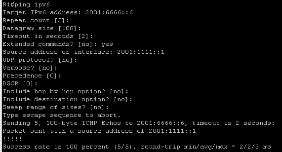
The ping test confirms that the connectivity has been established between R1 and R6's loopback IPs.
6VPE is defined in RFC 4659.
There is another technology called "6PE". The difference between "6PE" and "6VPE" is that
In the 6VPE, Customer's IPv6 routes are in specific VRF and exchanged through VPNv6 BGP address family.
In the 6PE, Customer's IPv6 routes are in global routing table and they are carried over using IPv6+label BGP address family.
More information on this can be found from http://www.cisco.com/c/en/us/td/docs/net_mgmt/ip_solution_center/6-0/mpls_vpn/user/guide/mpls60book/ipv6.html
In our last post, we have seen how we can configure standard Layer 3 MPLS connection on Cisco routers and advertise customer's IPv4 prefixes over that.
We will use the same topology for 6VPE however we will configure IPv6 addresses between PE to CE (R1-R2 and R5-R6) and on the Loopbacks of the CEs (R1 and R6).
This is how our topology looks like
We have used IPv6 ranges 2001:AA12::/64 between R1-R2 and 2001:BB56::/64 between R5-R6.
The loopbacks have been configured with 2001:1111::1/64 and 2001:6666::6/64 on R1 and R6 respectively.
Our aim to establish connectivity between these loopbacks over the backbone which is configured with IPv4 and runs OSPF+MPLS.
Ok so let's start the configuration
1. First, we will enable the IPv6 routing on CEs and configure the required interfaces with IPv6 addresses.
2. Now we will enable IPv6 on PEs and configured address-family IPv6 for VRF CUST1.
To support IPv6 VRF, we will remove the existing "ip vrf CUST1" configuration and reconfigure VRF with "VRF definition" command.
We have used RD as 100:1 and RT value for both import and export as 100:100. If we need to configure the IPv4 parameters for VRF CUST1, it can be done under "address-family ipv4".
Let's apply the similar config on R5.
3. The next step is to establish BGP neighbourship between PE and CE and advertise loopback IP from the CEs.
On the CEs
On the PEs
The PEs have now started receiving the loopback prefix in their BGP table.
However the PEs do not pass these prefix update to each other.
4. We will have to activate a VPNv6 neighbourship between PEs using the existing local IPv4 loopback addresses.
So the configuration will be
We can see that both the PEs now receive the loopback prefixes from each other.
Notice the next hop ::FFFF:5.5.5.5! The loopback IP 5.5.5.5 got converted into the IPv6 format.
Looking at R1's IPv6 routing table, we can see that it receives the loopback prefix of R6.
The ping test confirms that the connectivity has been established between R1 and R6's loopback IPs.
6VPE is defined in RFC 4659.
There is another technology called "6PE". The difference between "6PE" and "6VPE" is that
In the 6VPE, Customer's IPv6 routes are in specific VRF and exchanged through VPNv6 BGP address family.
In the 6PE, Customer's IPv6 routes are in global routing table and they are carried over using IPv6+label BGP address family.
More information on this can be found from http://www.cisco.com/c/en/us/td/docs/net_mgmt/ip_solution_center/6-0/mpls_vpn/user/guide/mpls60book/ipv6.html


No comments:
Post a Comment