In this post we will look at the steps of configuring Layer 3 MPLS VPN on Cisco routers.
As shown in the diagram, R1 and R6 are CE routers. R2 and R5 are PEs while R3 and R4 are P routers.

Let's go through the steps to configure this topology
1) Run IGP between the ISP routers (R2,R3,R4 and R5), advertise loopbacks of the PEs in IGP and enable MPLS.


We have configured OSPF on all the ISP routers and enabled MPLS by using the "mpls ldp autoconfig". We can ping to 5.5.5.5 (R5) from 2.2.2.2(R2).

The traceroute confirm that MPLS is enabled on all the ISP routers. I have configured "mpls label range x01 - x99" command on all the CPEs where x is the router number. e.g. R3 will use label number from 301 to 399.
2) Establish IBGP neighbourship between PE loopbacks
We will now establish an IBGP neighbourship between R2's Loopback and R5's Loopback


3) Configure VRF "CUST1" on the PEs and assign the interface towards CPE in this VRF
Let's configure the VRF on the PEs and assign the interfaces towards R1 and R6 in the VRF.


4) Activate VPNv4 neighbourship between PEs


5) Establish EBGP neigborship between PEs and CEs
On R2 and R5 we have to configure BGP under the address-family.


However on R1 and R6 the commands will go under the normal BGP process as there is no VRF configured on them. We will use AS 10 on R1 and AS 20 on R2.


We can see the BGP neighbours are up on both the routers.


6) Advertise LAN subnets into the BGP from the CEs
Now let's advertise the loopbacks 1.1.1.1/24 and 6.6.6.6/24 in BGP from R1 and R6 respectively.


Ok, now let's check the routing table on R1

We can see that R1 has started receiving the prefix 6.6.6.0/24 through BGP which means the control plane is ok.
Let's check the connectivity

This proves that the data plane is also working fine.
The traceroute from R1 shows the MPLS labels used by ISP routers to forward the traffic.
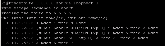
This shows that R5 has informed R2 to use the VPN label 504 for the traffic destined to 10:1:6.6.6.0/24. (10:1 is the RD configured in VRF CUST1). We can verify that from the below output


On R2 we can notice that the next-hop of the route 6.6.6.0/24 is seen as 5.5.5.5 which is the loopback ip on R5.

The labels 303 and 402 are used as transport label by R2 and R3 respectively to reach 5.5.5.5.


There is no transport label used by R4 as it pops the transport label (PHP).

Similarly one can find the relevant VPN and transport labels for the prefix 1.1.1.1/32.
As shown in the diagram, R1 and R6 are CE routers. R2 and R5 are PEs while R3 and R4 are P routers.
Let's go through the steps to configure this topology
1) Run IGP between the ISP routers (R2,R3,R4 and R5), advertise loopbacks of the PEs in IGP and enable MPLS.
We have configured OSPF on all the ISP routers and enabled MPLS by using the "mpls ldp autoconfig". We can ping to 5.5.5.5 (R5) from 2.2.2.2(R2).
The traceroute confirm that MPLS is enabled on all the ISP routers. I have configured "mpls label range x01 - x99" command on all the CPEs where x is the router number. e.g. R3 will use label number from 301 to 399.
2) Establish IBGP neighbourship between PE loopbacks
We will now establish an IBGP neighbourship between R2's Loopback and R5's Loopback
3) Configure VRF "CUST1" on the PEs and assign the interface towards CPE in this VRF
Let's configure the VRF on the PEs and assign the interfaces towards R1 and R6 in the VRF.
4) Activate VPNv4 neighbourship between PEs
5) Establish EBGP neigborship between PEs and CEs
On R2 and R5 we have to configure BGP under the address-family.
However on R1 and R6 the commands will go under the normal BGP process as there is no VRF configured on them. We will use AS 10 on R1 and AS 20 on R2.
We can see the BGP neighbours are up on both the routers.
6) Advertise LAN subnets into the BGP from the CEs
Now let's advertise the loopbacks 1.1.1.1/24 and 6.6.6.6/24 in BGP from R1 and R6 respectively.
Ok, now let's check the routing table on R1
We can see that R1 has started receiving the prefix 6.6.6.0/24 through BGP which means the control plane is ok.
Let's check the connectivity
This proves that the data plane is also working fine.
The traceroute from R1 shows the MPLS labels used by ISP routers to forward the traffic.
This shows that R5 has informed R2 to use the VPN label 504 for the traffic destined to 10:1:6.6.6.0/24. (10:1 is the RD configured in VRF CUST1). We can verify that from the below output
On R2 we can notice that the next-hop of the route 6.6.6.0/24 is seen as 5.5.5.5 which is the loopback ip on R5.
The labels 303 and 402 are used as transport label by R2 and R3 respectively to reach 5.5.5.5.
There is no transport label used by R4 as it pops the transport label (PHP).
Similarly one can find the relevant VPN and transport labels for the prefix 1.1.1.1/32.
No comments:
Post a Comment