In this post, we will discuss about MPLS Traffic Engineering. To understand where it can be used and what problems it can resolve, let's look at the below topology.

The CE1 and CE2 are customer edge devices with LAN subnet of 1.1.1.1/32 and 7.7.7.7/32 respectively. They are connected with corresponding PE1 and PE2. We are running OSPF and LDP in the service provider core. Both the PE devices exchange VPN labels via MP-BGP and transport label via LDP.
In normal condition, if a packet originates from 1.1.1.1 towards 7.7.7.7, it will reach PE1. PE1 would forward it to P1 based on the OSPF cost to reach PE2. The reason packet will not be forwarded to P2 is because OSPF calculates the least cost path through P1.
The problem here is that the backup path through P2 and P3 will sit idle which will result in waste of bandwidth. We cannot solve this problem by manipulating the IGP metric. What can be done to resolve this issue?
We can use RSVP-TE and CSPF (Constrained SPF) to overcome this issue through MPLS Traffic Engineering.
RSVP was used in the Inteserve model of QoS. It is modified to support MPLS which is known as RSVP-TE.
CSPF is used to overcome the limitations of normal OSPF explained in the above topology. Normally OSPF uses bandwidth to calculate the metric however CSPF uses additional factors such as affinity, administrative weight and explicitly defined path as well.
Now let's see how we can use MPLS-TE in our topology.
At the moment, if we traceroute to 7.7.7.7 from CE1 with the source as 1.1.1.1, we can see the traffic goes through P1.

Similarly traceroute from CE2 to CE1 takes the same path based on the best IGP metric.

In normal situation, it's not possible to use the path through PE1-P2-P3-PE2 due to the high OSPF cost.
By using MPLS-TE, we can force the traffic to use this alternate path through P2 and P3.
The first step is to enable MPLS-TE support globally on all the routers within service provider environment. I have just shared the output from PE1 for brevity.

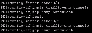
Next step is to enable the MPLS TE support and RSVP on the individual interfaces on all the devices.

You can also specify the amount of interface bandwidth (in kbps) allocated for RSVP flows. In our case we have just simply enabled the RSVP.
RSVP assigns labels to the LSPs. The headend of the tunnel (PE1 in our scenario) sends PATH messages towards tailend (PE2). The tailend sends RESV messages with a lable towards headend.
The third step is to enable TE support in IGP.

We have first configured the router-id as local loopback (must be /32) and enabled TE in area 0. Again this needs to be done on all the devices.
Now we will configure the TE tunnel interface. We will build the tunnel between PE1 and PE2.


The command "autoroute announce" is used to advertise the TE tunnel into the IGP. We can also configure a static route for the tunnel destination through the tunnel interface.
The command "path-option xx dynamic" makes the tunnel use a path which is dynamically calculated. The number xx (10 in our case) is the preference for this path option. It can be used in the scenario where we have multiple paths configured.
The TE tunnel should be up and running now. We can verify it as below.

I have just shown a part of the output here which confirms that TE tunnel is up and running.
If we do a traceroute from CE1 to CE2 again

The packets are still going through P1 however the label numbers are now different than the previous traceroute.
In the above output, 23 is the VPN label and 25 is the label assigned for tunnel. This can be verified by the below.

 This confirms that the traffic is going through the tunnel however it's still going through P1. We will have to configure explicit-path option to force the traffic to follow the path through P2 and P3.


Similar config on PE2

Below output confirms that the traffic is using the spare link now.


You may have to bounce the tunnel interface for the new path to take effect.
More information on MPLS TE can be found on http://www.cisco.com/c/en/us/td/docs/switches/datacenter/sw/5_x/nx-os/mpls/configuration/guide/mpls_cg/mp_te_basic.html

The CE1 and CE2 are customer edge devices with LAN subnet of 1.1.1.1/32 and 7.7.7.7/32 respectively. They are connected with corresponding PE1 and PE2. We are running OSPF and LDP in the service provider core. Both the PE devices exchange VPN labels via MP-BGP and transport label via LDP.
In normal condition, if a packet originates from 1.1.1.1 towards 7.7.7.7, it will reach PE1. PE1 would forward it to P1 based on the OSPF cost to reach PE2. The reason packet will not be forwarded to P2 is because OSPF calculates the least cost path through P1.
The problem here is that the backup path through P2 and P3 will sit idle which will result in waste of bandwidth. We cannot solve this problem by manipulating the IGP metric. What can be done to resolve this issue?
We can use RSVP-TE and CSPF (Constrained SPF) to overcome this issue through MPLS Traffic Engineering.
RSVP was used in the Inteserve model of QoS. It is modified to support MPLS which is known as RSVP-TE.
CSPF is used to overcome the limitations of normal OSPF explained in the above topology. Normally OSPF uses bandwidth to calculate the metric however CSPF uses additional factors such as affinity, administrative weight and explicitly defined path as well.
Now let's see how we can use MPLS-TE in our topology.
At the moment, if we traceroute to 7.7.7.7 from CE1 with the source as 1.1.1.1, we can see the traffic goes through P1.
Similarly traceroute from CE2 to CE1 takes the same path based on the best IGP metric.
In normal situation, it's not possible to use the path through PE1-P2-P3-PE2 due to the high OSPF cost.
By using MPLS-TE, we can force the traffic to use this alternate path through P2 and P3.
The first step is to enable MPLS-TE support globally on all the routers within service provider environment. I have just shared the output from PE1 for brevity.
Next step is to enable the MPLS TE support and RSVP on the individual interfaces on all the devices.
You can also specify the amount of interface bandwidth (in kbps) allocated for RSVP flows. In our case we have just simply enabled the RSVP.
RSVP assigns labels to the LSPs. The headend of the tunnel (PE1 in our scenario) sends PATH messages towards tailend (PE2). The tailend sends RESV messages with a lable towards headend.
The third step is to enable TE support in IGP.

We have first configured the router-id as local loopback (must be /32) and enabled TE in area 0. Again this needs to be done on all the devices.
Now we will configure the TE tunnel interface. We will build the tunnel between PE1 and PE2.


The command "autoroute announce" is used to advertise the TE tunnel into the IGP. We can also configure a static route for the tunnel destination through the tunnel interface.
The command "path-option xx dynamic" makes the tunnel use a path which is dynamically calculated. The number xx (10 in our case) is the preference for this path option. It can be used in the scenario where we have multiple paths configured.
The TE tunnel should be up and running now. We can verify it as below.

I have just shown a part of the output here which confirms that TE tunnel is up and running.
If we do a traceroute from CE1 to CE2 again
The packets are still going through P1 however the label numbers are now different than the previous traceroute.
In the above output, 23 is the VPN label and 25 is the label assigned for tunnel. This can be verified by the below.
Similar config on PE2
Below output confirms that the traffic is using the spare link now.
You may have to bounce the tunnel interface for the new path to take effect.
More information on MPLS TE can be found on http://www.cisco.com/c/en/us/td/docs/switches/datacenter/sw/5_x/nx-os/mpls/configuration/guide/mpls_cg/mp_te_basic.html
Excellent, never saw TE in lab myself. So it is good starting point. Thanks for short and nice blog about MPLS-TE and where to use.
ReplyDelete