In this post we will look at the Carrier Supporting Carrier design where smaller service providers use large service providers as backbone in order to connect parts of their network which eliminates the need to build and maintain their own MPLS network.
From customer's point of view, there is no difference in terms of connectivity and it will still appear as they have a normal Layer 3 MPLS connection from the provider.
Let's look at the below topology to understand how it works.

We have a Tier 2 SP who is providing services to customer sites in two different geographical locations. The service provider have their own network within specific regions but not connected with each other directly hence they are using Tier 1 SP's backbone to connect both of their networks and provide end-to-end connectivity to the customer.
As shown in the diagram the Tier 2 SP have a route-reflector in each region. Our end goal is to establish VPNv4 neighbourship between these route-reflectors to exchange the routing information.
From the configuration prospective, these are the loopback IPs configured on various devices.
CE1 = 1.1.1.1/32 (Customer LAN prefix)
CE2 = 15.15.15.15/32 (Customer LAN prefix)
SP-PE1 = 2.2.2.2/32
SP-PE2 = 14.14.14.14/32
SP-RR1 = 4.4.4.4/32
SP-RR2 = 12.12.12.12/32
Tier 2 SP uses BGP AS 100 on the PEs at both the locations and run OSPF as the IGP. Tier 1 SP uses ISIS as IGP and BGP AS 200 on the PEs.
At the moment, CE1 is advertising the loopback IP to SP-PE1. SP-PE1 advertise the VPNv4 route to route-reflector SP-RR1 which then gets learned by CSC-CE1.


Similarly CE2 is advertising the prefix 15.15.15.15/32 and it's learned by CSC-CE2 through SP-RR2.

We need to establish VPNv4 IBGP neighbourship between both the route reflectors. For that we need to exchange the loopback IPs of RRs using the Tier1 SP network.
As we can see from the diagram, Tier 1 SP network has CSC-PE1 and CSC-PE2 devices and there is a separate VPNv4 BGP neighbourship between both of them.


These devices are directly connected to Tier2 CSC-CE devices. Tier1 SP will treat them as end customer CE router. We have configured a separate VRF "CSC" on both CSC-PE1 and CSC-PE2 and have added the interfaces towards CSC-CE devices under that VRF.


While on CSC-CE1 and CSC-CE2 there isn't any special configuration under the interface facing Tier1 PE routers.


We can advertise the loopback IPs of route reflectors from CSC-CE routers to CSC-PE router by using BGP+Label or LDP+IGP. We will use BGP+Label in this case.
so the configuration on the CEs


Let's advertise the prefixes in BGP using the "network" statement. In real world we should use prefix-list to control the subnets which are getting redistributed.
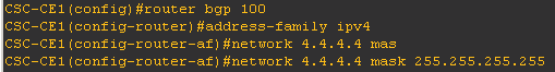

As we will be receiving the prefix from the same BGP AS 100 on the CEs, we configured "allowas-in" to get around BGP's default loop prevention mechanism.
The configuration on the CSC-PEs


The output on the CSC-PEs shows that we have started receiving the prefixes


The CSC-CEs also started receiving the updates from relevant CSC-PEs


Now we have redistribute these BGP routes into local IGP for them to propagate through the network.


The route-reflectors have now learned the prefix


We will configure VPNv4 IBGP neighbourship between both route-reflectors


we can see that the RRs have started passing the routing updates however the prefix learned is not the best route.

The route is learned with the next-hop being the remote end PE router. The loopback of PE router has not been learned via IGP hence the route is not installed in the routing table.

We will have to advertise the loopback of PE routers as well through BGP.


Now we can see that the route is considered as the best route.


The RRs will pass this update to both the PEs which will eventually be passed onto the CE routers.


The ping and traceroute confirm that there is a full reachability.


Let's now analyse the above output and figure out how MPLS label exchange worked.

From customer's point of view, there is no difference in terms of connectivity and it will still appear as they have a normal Layer 3 MPLS connection from the provider.
Let's look at the below topology to understand how it works.

We have a Tier 2 SP who is providing services to customer sites in two different geographical locations. The service provider have their own network within specific regions but not connected with each other directly hence they are using Tier 1 SP's backbone to connect both of their networks and provide end-to-end connectivity to the customer.
As shown in the diagram the Tier 2 SP have a route-reflector in each region. Our end goal is to establish VPNv4 neighbourship between these route-reflectors to exchange the routing information.
From the configuration prospective, these are the loopback IPs configured on various devices.
CE1 = 1.1.1.1/32 (Customer LAN prefix)
CE2 = 15.15.15.15/32 (Customer LAN prefix)
SP-PE1 = 2.2.2.2/32
SP-PE2 = 14.14.14.14/32
SP-RR1 = 4.4.4.4/32
SP-RR2 = 12.12.12.12/32
Tier 2 SP uses BGP AS 100 on the PEs at both the locations and run OSPF as the IGP. Tier 1 SP uses ISIS as IGP and BGP AS 200 on the PEs.
At the moment, CE1 is advertising the loopback IP to SP-PE1. SP-PE1 advertise the VPNv4 route to route-reflector SP-RR1 which then gets learned by CSC-CE1.
Similarly CE2 is advertising the prefix 15.15.15.15/32 and it's learned by CSC-CE2 through SP-RR2.
We need to establish VPNv4 IBGP neighbourship between both the route reflectors. For that we need to exchange the loopback IPs of RRs using the Tier1 SP network.
As we can see from the diagram, Tier 1 SP network has CSC-PE1 and CSC-PE2 devices and there is a separate VPNv4 BGP neighbourship between both of them.
These devices are directly connected to Tier2 CSC-CE devices. Tier1 SP will treat them as end customer CE router. We have configured a separate VRF "CSC" on both CSC-PE1 and CSC-PE2 and have added the interfaces towards CSC-CE devices under that VRF.
While on CSC-CE1 and CSC-CE2 there isn't any special configuration under the interface facing Tier1 PE routers.
We can advertise the loopback IPs of route reflectors from CSC-CE routers to CSC-PE router by using BGP+Label or LDP+IGP. We will use BGP+Label in this case.
so the configuration on the CEs
Let's advertise the prefixes in BGP using the "network" statement. In real world we should use prefix-list to control the subnets which are getting redistributed.
As we will be receiving the prefix from the same BGP AS 100 on the CEs, we configured "allowas-in" to get around BGP's default loop prevention mechanism.
The configuration on the CSC-PEs
The output on the CSC-PEs shows that we have started receiving the prefixes
The CSC-CEs also started receiving the updates from relevant CSC-PEs
Now we have redistribute these BGP routes into local IGP for them to propagate through the network.
The route-reflectors have now learned the prefix
We will configure VPNv4 IBGP neighbourship between both route-reflectors
we can see that the RRs have started passing the routing updates however the prefix learned is not the best route.
The route is learned with the next-hop being the remote end PE router. The loopback of PE router has not been learned via IGP hence the route is not installed in the routing table.
We will have to advertise the loopback of PE routers as well through BGP.
Now we can see that the route is considered as the best route.
The RRs will pass this update to both the PEs which will eventually be passed onto the CE routers.
The ping and traceroute confirm that there is a full reachability.
Let's now analyse the above output and figure out how MPLS label exchange worked.
Following happens
for a packet originating from CE1 and terminating at CE2.

1.
SP-PE1 (PE router
attached to CE1)
Outgoing Transport label is 21
VPN label is 19
next-hop is SP-PE2 (14.14.14.14)
2.
SP-P1 (P
router)
Outgoing Transport label is 17
VPN label is 19
next-hop is SP-PE2 (14.14.14.14)
3.
CSC-CE1 (CE
router connected to Tier 1 SP PE device)
Outgoing Transport label is 21
VPN label is 19
next-hop is SP-PE2 (14.14.14.14)
4.
CSC-PE1 Tier 1 Carrier PE router
Outgoing CSC transport label is 17
CSC VPN label is 20 (The transport label becomes
the CSC VPN label)
VPN label is 19
next-hop is CSC-PE2 (10.10.10.10)
5.
CSC- P1 Tier 1
Carrier P router
Outgoing CSC transport label is 17
CSC VPN label is 20
VPN label is 19
next-hop is CSC-PE2 (10.10.10.10)
6.
CSC- P2 Tier 1
Carrier P router
Outgoing CSC transport label is 16
CSC VPN label is 20
VPN label is 19
next-hop is CSC-PE2 (10.10.10.10)
7.
CSC- P3 Tier 1
Carrier P router
Outgoing CSC transport label removed
CSC VPN label is 20
VPN label is 19
next-hop is CSC-PE2 (10.10.10.10)
8.
CSC- PE2 Tier 1 Carrier PE router
Outgoing transport label is 19
VPN label is 19
next-hop is SP-PE2 (14.14.14.14)
9.
CSC-CE2(CE router
connected to Tier 1 SP PE device)
Out going transport label is 16
VPN label is 19
next-hop is SP-PE2 (14.14.14.14)
10. SP-P2 (P
router)
Outgoing transport label is removed
VPN label is 19
next-hop is SP-PE2 (14.14.14.14)
11.SP-PE2 (PE
router attached to CE2)
VPN label is removed
destination reached in next-hop
More information can be found on http://www.cisco.com/c/en/us/td/docs/ios/12_2s/feature/guide/fs2scsc.html
No comments:
Post a Comment