If you are working for a service provider then you may have
seen that it is quite a common practice to install two circuits and two CPEs at a
customer site for the resiliency purpose. One of these circuits act as primary
and carry all the inbound/outbound traffic. The second circuit acts as a backup
and not used unless the primary circuit or the CPE fails.
Here is the diagram showing the scenario

On customer Site A, we have two CPEs, R2 as the primary and R3
as the backup. R1 represents a customer device on the LAN. This customer has another remote office Site B
which is shown as R5 (Single CPE). R4 is the service provider router.
We run OSPF running between R1, R2 and R3 (Site A LAN).
There are EBGP peering between R2 – R4, R3 – R4 and R4 – R5. I have done mutual
redistribution between OSPF and BGP on R2 and R3. R2 and R3 advertise 2.2.2.0/24 (Loopback 2 of R5) in OSPF with metric 10 and 20 respectively. Similarly both the
routers advertise 10.1.123.0/24( Site A LAN subnet) into BGP with MED 10 and 20
respectively.

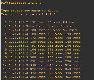
We can see that loopback 2 of R5 is reachable via R2
(primary) which is expected. The traceroute confirms that

Let’s check how R5’s routing table looks like

We learn the Site A’s LAN subnet 10.1.123.0/24 via BGP.
Let’s do a traceroute with the source loopback 2.

This confirms that the return path of the traffic is also
via R2 (primary).
Now let’s say customer wants to utilize their backup link on
Site A. They want the traffic from Site A to Site B and vice versa to go over
the R3. How do we achieve this?
Let’s look at the outbound direction from Site A first, all
the traffic destined for the loopback go via R2. If we can match the
destination (i.e. 2.2.2.0/24) and redirect that traffic to R3 then our outbound
traffic will flow as customer wants.
To do this let’s create an ACL which matches the destination
on R2.
Let’s create a route-map which matches this ACL and set the
next-hop to R3.

Now, we will enable policy based routing on R2.

Now let’s verify the connectivity from R1 to loopback 2.

This output proves that the traffic destined for for 2.2.2.2
goes through R3.
All OK ?? Not really !!!!
What if we shutdown LAN interface of R3?

We can see that the traffic is getting blackholed. The
reason being that even though R3’s LAN interface is down, R2 keeps forwarding
the traffic destined to Loopback 2 towards R3 because of the policy routing. We
need to make sure that if R3’s LAN is unreachable then PBR doesn’t come into
effect.
To achieve this, Let’s track the status of R3’s LAN by using
IP SLA and tracking the status of R3’s LAN.

Now we can modify the route-map PBR and add the track option

So let’s try again….
I have unshut R3’s LAN interface so the traffic is going
through R3

Now let’s shut down the LAN interface of R3

Now we can see that it’s going via R2

Is everything ok now?? Unfortunately NO….
What if R3’s WAN interface goes down? We are tracking the
LAN of R3 so if the WAN interface goes down then the packet will loop between
R2 and R3. Let’s see that in action….

So how do we resolve this issue?
Let’s track WAN IP of R3 from R2. So we will have to modify
the IP SLA object.

We also have to create a static route saying that this IP is
reachable via LAN interface
Now, let’s try again….

Traceroute from R1

What if the WAN interface of R3 stays up but the circuit
goes down? We will cover that in the second part of the post.
Feel free to comment/suggest.......
No comments:
Post a Comment